#LED with Button Control in STM32 using STM32
Explore tagged Tumblr posts
Visit Tumblr Blog
Explore Tumblr blogs with no restrictions, modern design and the best experience.
Last Seen Tumblr Blogs


Fun Fact
Tumblr has 4 main sources of revenue.
Text
Getting Started with Embedded Systems Programming

Embedded systems programming is the backbone of modern electronics. From smartwatches to washing machines, embedded systems power the intelligent functions of countless everyday devices. This guide will introduce you to the basics of embedded programming, key tools, and how to begin building your own embedded applications.
What is an Embedded System?
An embedded system is a computer integrated into a larger system or device, performing dedicated functions. Unlike general-purpose computers, embedded systems are designed for specific tasks, often with constraints on power, memory, and processing.
Examples of Embedded Systems:
Microcontrollers in home appliances
Sensor-based devices (e.g., temperature sensors, motion detectors)
Medical equipment
Automotive control systems
IoT (Internet of Things) gadgets
Core Components of an Embedded System
Microcontroller or Microprocessor: The brain of the embedded system (e.g., Arduino, STM32, ESP32).
Memory: RAM and ROM to store instructions and data.
Input/Output Interfaces: Connects to sensors, displays, motors, and communication modules.
Software: Custom firmware developed for specific functions, typically in C or C++.
Popular Programming Languages
C: Most widely used due to its efficiency and low-level hardware access.
C++: Used when object-oriented design is required.
Assembly: For highly optimized or time-critical routines.
MicroPython: Python for microcontrollers (e.g., ESP8266, Micro:bit).
Getting Started with Embedded Programming
Select Your Platform:
Beginners: Arduino (easy setup, wide community support)
Advanced: STM32, Raspberry Pi Pico, ESP32
Set Up Your Development Environment:
Install IDEs like Arduino IDE, PlatformIO, STM32CubeIDE
Download necessary drivers and board support packages
Write and Upload Code: Create simple programs like blinking an LED, then expand to sensors, displays, and communication modules.
Example: Blink an LED with Arduino
void setup() { pinMode(13, OUTPUT); // Set pin 13 as output } void loop() { digitalWrite(13, HIGH); // Turn LED on delay(1000); // Wait for 1 second digitalWrite(13, LOW); // Turn LED off delay(1000); // Wait for 1 second }
Tools and Debugging
Serial Monitor: For real-time debugging and logging.
Oscilloscope & Logic Analyzer: For electrical signal inspection.
In-Circuit Debuggers: Like JTAG or ST-Link for low-level debugging.
Best Practices
Write modular and readable code.
Use debouncing for physical inputs like buttons.
Handle memory carefully to avoid overflows.
Optimize power usage in battery-powered devices.
Conclusion
Embedded systems programming is both fun and powerful, offering endless possibilities for innovation in hardware and software. Whether you’re building a home automation project or diving into the world of IoT, understanding the basics of embedded programming gives you the foundation to create smart, responsive devices.
0 notes
Link
0 notes
Text
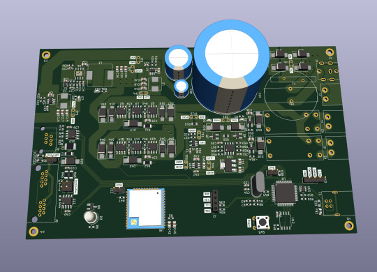
Let me introduce my current main WIP. It's not fandom related, it's for my model railroad, and it's not yet finished.
This is a rendering of a circuit board that I'm designing at the moment. It will be a DCC command station. My model railroad is run digitally, which means the tracks carry digital signals that tell each locomotive and switch individually how to run, which lights to turn and so on. The command station is the device that generates that. I have a number of different layouts, one of which has a good command station, one of which has a crappy old one, and the final one isn't even digital yet. So this will be the one that solves all issues for me, hopefully.
The design above isn't finished yet, and even the parts that are are not yet fully representative. The different capacitors are just there as options; some screen print overlaps; and some components (in particular all plugs and the relays that control the programming track) don't have 3D models so they don't show up.
Planned features:
Four layer board
10-25 V DC output, software controllable
Up to 5A output power, limited mainly by the main switching regulator.
Input 15-25V either AC or DC with polarity protection, selectable with some solder bridges (not yet in there). Optionally you can also bypass the main power regulator with another solder bridge (that I haven't added yet); useful in case you use e.g. a laptop power supply with a switchable voltage and don't need any regulation after that.
Railcom support
USB connection; not yet sure what for, but the main chip I'm using has USB support and I have some spare USB connectors here, so in it goes.
Speaking: The chip is an STM32L433RCT6P, chosen because I found it in stock at an electronics distributor. 64 kB RAM, 256 kB EEPROM, with support for an additional up to 256 MB externally (there's a spot for that on the board) and lots of fun extras that I don't technically need. It has an FPU! I don't need an FPU, but I will definitely do some floating point math computation on it just for fun.
Main external connection is WLAN using an ESP32 WROOM U module. I haven't decided on the housing, but I may go for extruded aluminum, so it's the U version that allows and requires an external antenna
It supports XBUS/XpressNet connections for old throttles from Lenz and Roco that I should probably throw away, but I paid good money for them, dang it.
It supports CAN for LCC / OpenLCB. I may not populate this part on all boards that I'm building, because I haven't actually decided whether I am interested. But the chip has CAN functionality built in, so why not.
There's an I2C connection to connect a cheap tiny OLED display for status messages.
Test points for all important signals (in particular the different internal voltage levels; yes, there is 3.3V, A3.3V and -3.3V and I need all of them).
Stuff still to add:
I will add pin headers (or space for pin headers anyway) for all the remaining pins on the STM32, and perhaps some on the ESP32, for future expansions.
Status LED and stop/go button on the front
Wire it all up, maybe move some stuff (mostly the STM32 around), which will cause all sorts of fun new routing issues.
Adjustments to make the jacks line up with the front panel once I've decided on a housing.
Features I'm not considering adding:
s88. I vaguely know what it is but I don't have any devices like that, and if that ever changed I could probably build (or perhaps buy) a converter that connects them via CAN.
Other buses like LocoNet.
Ethernet. I don't need it and it's actually more expensive than WLAN in this day and age.
In terms of software, I'm planning to use DCC-Ex on it. The whole project actually started out as a DCC-Ex shield, but once I realised that this wouldn't fit, I decided to make it standalone. Now, DCC-Ex is designed for Arduino, not STM32, and it doesn't support XpressNet, nor OpenLCB, nor Railcom, and their Wifi protocol is pretty weird and annoying which will be an issue (I'm planning to write my own control app for iPhone for it), so I'll probably change that or just replace it with the z21 one… so really, the software will not look a lot like DCC-Ex once I'm done with it.
Will this all work? I have honestly no idea. I mean, I'm fairly confident, I'd have given up on this long ago otherwise, but I have no guarantees either way until I've spent a lot of money on components and circuit boards and start soldering. Turns out doing it this way is not really cheaper than just buying a half-way decent one. That's what makes it exciting, though!
If it does work, obviously this will be released as open source. But it's still going to be a few days (more realistically weeks) before it's even ready to order the parts, and then a lot of soldering (current BOM stands at 194 actual components), and then a lot of software development before it's ready for that.
5 notes
·
View notes
Text
Nucleo f401re clion

#NUCLEO F401RE CLION CODE#
#NUCLEO F401RE CLION SERIES#
#NUCLEO F401RE CLION FREE#
PC0, PC1, PC2, PC3, PC10, PC11, PC12, PC13, PC14, PC15Ĭan be used to power them module from battery They are also categorized with the table below: The name of the pins can be found in the image above. They comprise of GPIO pins, Analog Pins, Timer Pins, and Power pins. These pins are classified into CN7 and CN10 with each having 38 Pins. These pins can also be used for I2C Communication A4 is SDA and A5 is SCLĬan be used to provide analog reference voltageĪcts as SCK, MISO, MOSI and CS pins respectively for SPI communicationĪcts as Rx and Tx pins respectively for USART communicationĪpart from the Arduino pins, the board also has 76 (38+38) GPIO pins as male headers on either side of the board as shown above. Provides 3.3V as output can also be used to power the MCU Each category pin can be tabulated as follows: The Arduino pins are split into category CN5, CN6, CN8, and CN9. The arduino like pins are female connector pins which exactly match the order and position of Arduino UNO pins and hence any Arduino shield can be used with these development boards. The pin one resembles the Arduino UNO and the blue one is the STM32 style ( Morpho). As you can see, there are two sets of pins. The STM32 Nucleo board pinout is shown above. The Board operates with 3.3V supply but a wide voltage range of 7-12V can be provided to the VIN pin since it has an on-board voltage regulator. Similarly, there are two push buttons where one is user programmable, and the other is to reset the Microcontroller. This board also comes with an integrated ST-LINK/V2-1 programmer and debugger hence it is very easy to get started with this board.Īs shown in the image above, there are three LEDs, where LD1 is for indicating USB communication, LD2 is programmable LED, and LD3 indicates power. The Boards pinout is similar to Arduino UNO and has many other additional pins to expand performance. It features the ARM Cortex M4 32-bit STM32F401RET6 microcontroller which is in LQFP64 package. Errors and Warnings List: The left pane shows the list of errors and warnings and some hints are provided inside the code.The STM32 Nucleo boards are the official Development Boards from STMicroelectronics.
#NUCLEO F401RE CLION CODE#
The code is checked as you type, with suggestions, help and error checking. Check-as-You-Type Code Control: This is really amazing.
#NUCLEO F401RE CLION SERIES#
ATmega-based Trinket boards from Adafruit, - Atmel ATmega- and Cortex-M3 SAM-based boards from Arduino, - Microchip PIC32-based chipKIT boards from Diligent, - Atmel ATmega328 with BLE BLuno board from DFRobot, - Atmel ATtiny85-based board from Digistump, - Intel Quark SoC X1000-based Galileo boards from Intel, - LaunchPad MSP430 and LaunchPad Cortex-M4 Tiva C series boards from Texas Instrument, - ARM Cortex-M3 STM32 F103RB-based board from Maple, - ATmel ATmega328 and ATmega644-based boards from Microduino, - ARM Cortex-M4 Freescale MK20-based Teensy 3.0 and 3.1 from PJRC, - Atmel ATmega644p-based board from Wiring, - Nordic nRF51822 SoC-based boards from RedBearLab, - Nucleo F401RE on mbed from STMicroelectronics, - Freedom KL25Z on mbed from FreescaleĬode Presentation: Syntax colouring, line numbering and function highlighting ease code reading.
#NUCLEO F401RE CLION FREE#
It eases development for the most popular embedded computing boards.Īfter having played with embedded computing platforms for a while, I was looking for one single IDE and a better one.īecause I'm a Mac user, I designed embedXcode, a template for Xcode, the free and standard IDE on Mac.ĮmbedXcode supports the most popular boards based on the Wiring / Arduino framework and on the mbed framework.
1 note
·
View note
Text
Using STONE TFT LCD Control WS2812B_RGB lamp
Using STONE TFT LCD Control WS2812B_RGB lamp
This article documented the process of controlling the WS2812B_RGB lamp using the STONE display module.
This project is to achieve RGB lamp control:
1. Change the color of the light
2. Change the brightness of the light
3. Change the four modes of the lamp

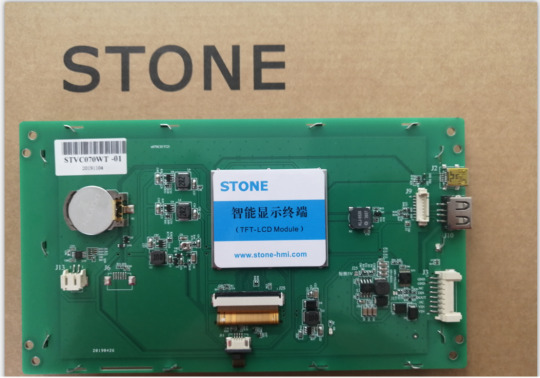
STONE TFT-LCD
The STONE STVC070WT-01 is a 7-inch display module with a resolution of 800*480.This display module can be purchased from the official website of STONE. The communication mode is uart-rs232 and uart-ttl.The development method is very simple, MCU only needs to send instructions to STONE display module to control the display content through UART. In the same principle, when the user touches the STONE display module, the display module also sends relevant instructions to MCU through UART, and MCU then controls the device (WS2812B_RGB lamp in this project).
STONE STVC070WT-01
The following picture shows the package and accessories I received:

LIST:
1. Connection and interface
2. USB to TTL adapter plate
3. Usb flash drive (including development information)
4. Micro USB cable
5. USB transfer board
6. STONE STVC070WT-01 display module
7. 12V power adapter
The function of the STONE TFT LCD
- built-in Cortex CPU and driver
- can be controlled by any single chip microcomputer
- show pictures/text/curves
-65536 color TFT display
- can be touched
- RS232/ RS485/ TTL UART interface and USB port
- wide voltage range
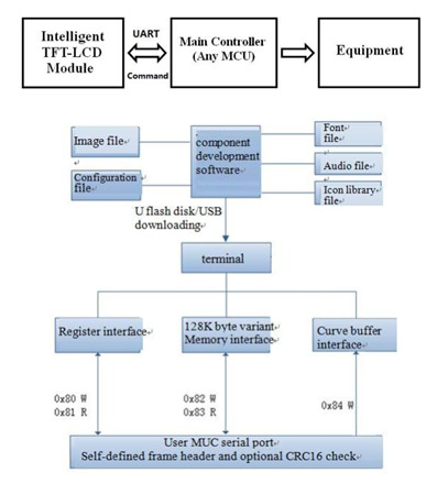
How the STONE tft-lcd display module works
The tft-lcd module communicates with the customer's MCU through commands (hexadecimal code), and the MCU then controls the connected device to work according to the commands received.
The development steps for the STONE module
Use STONE's tft-lcd module in only 3 steps:
l Design a beautiful set of graphical user interfaces.
l Connect directly to the client's MCU via RS232, RS485 or TTL.
l Write a simple program, by the MCU command control TFT-LCD module.(hex).
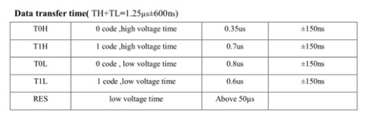
TFT LCD module serial command frame consists of 5 data blocks, all serial command or data are expressed in hexadecimal format.Data transfer in MSB mode.For example, for 0x1234, first send 0x12, then 0x34.
Application scenarios of STONE tft-lcd display module
The following 9 application scenarios are described on STONE's official website:
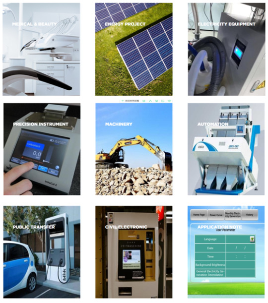
STONE display module is widely used in various industrial fields, such as:
Medical beauty equipment, construction machinery and vehicle equipment, electronic instruments, industrial control system, power industry, civil electronic equipment, automation equipment, transportation.
UI image design for STONE TFT-LCD
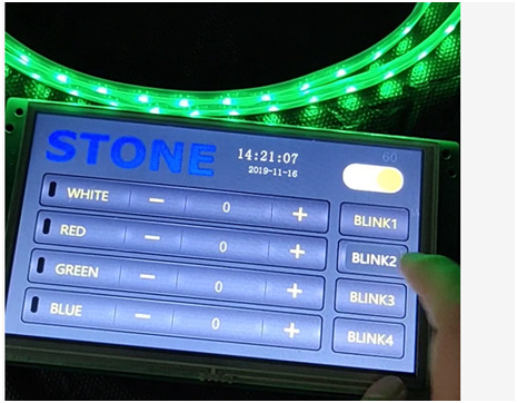
The interface designed by using Photoshop is as follows:
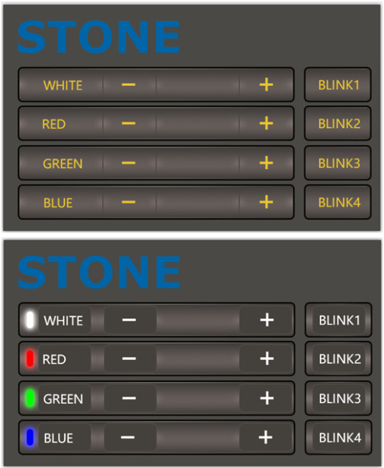
The first picture is the main screen picture, and the second picture is the effect when the button is pressed.
Use TOOL2019 software to generate LCD module configuration files
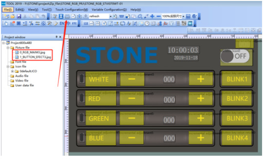
Click the button indicated by the arrow to generate the configuration file, and then download the configuration file into the display module to display the UI interface we designed.
This part of the content and tutorial I do not go into detail, you can go to STONE website to download a very detailed tutorial.
Wiring and welding
Having completed the touch display control above, we can focus on the development of MCU and WS2812B_RGB lamps.
But before that, we need to do some welding.
Wiring diagram
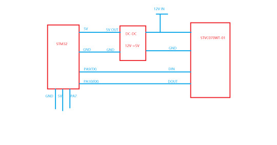
The power adapter is 12V, which needs to power the STONE STVC070WT-01 display module and to power the MCU module and WS2812B_RGB lamp by lowering the voltage to 5v through the dc-dc buck.
Accessories used in the project

Main accessories are:
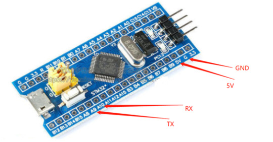
1. STM32F103C8R6 module
2. Dc-dc buck module
3. UART connection
Since the communication mode of STONE STVC070WT-01 is uart-ttl by default, we do not need the RS232 interface for the connection connection. Remove the RS232 interface:

welding
Weld these parts together and the effect is as follows:
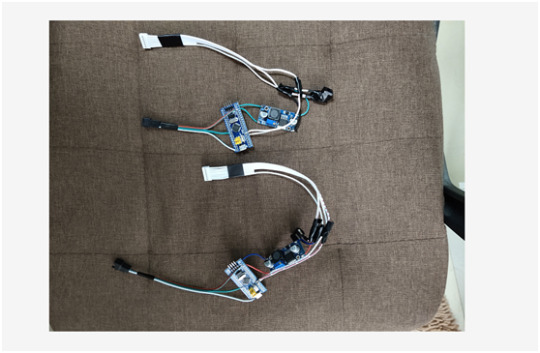
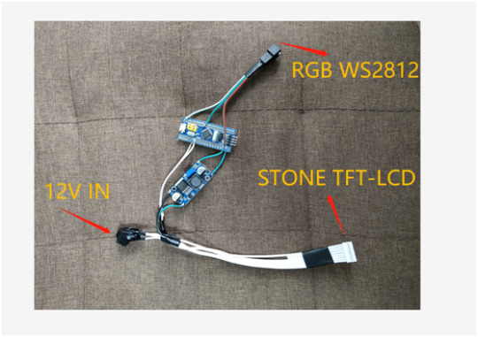
There are three interfaces, as shown above.
When this part is ready, you can program the MCU.But before we do that, we need to determine how the WS2812B_RGB lamp will be driven.
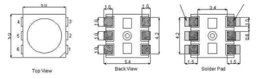
WS2812B
WS2812B is actually an RGB driver chip.
The control circuit and RGB chip are integrated in a 5050 package of components to form a complete pixel point.
Built-in signal shaping circuit, any pixel received the signal after waveform shaping output, to ensure that the waveform distortion of the circuit
Accumulation.
Built-in power on reset and power off reset circuit.
The color of each pixel can achieve 256 levels of brightness display, complete the full color display of 16777216 colors,
Serial interface, can complete data reception and decoding through a signal line.
The transmission distance between any two points is no more than 5 meters without any additional circuit.
When the refresh rate is 30 frames/SEC, the cascade number of low-speed mode should be no less than 512 points, and that of high-speed mode should be no less than 1024 points.
Data transmission speed up to 8Kbps.The color of the light is highly consistent and cost-effective.
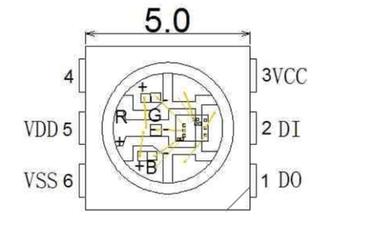
1 DOUT: Data output, control data signal output
2 DIN: Data input, control data signal input
3 VCC: Logic power supply, control circuit power supply
4 NC
5 VDD: Power supply, LED power supply
6 VSS: GND
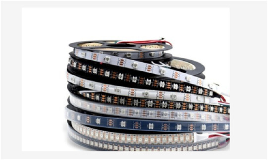
Application field
LED full-color light string, LED full-color module, LED full-color soft light bar hard light bar, LED guardrail tube, LED point light source, LED pixel screen, LED special-shaped screen, various electronic products, electrical equipment running horse light.
Driver for WS2812
The driving mode of WS2812 is simple. MCU only needs a signal line to complete the brightness and color control.
STM32 driver code
#include "../BOARD/ws2812/ws2812.h"
#include "usart.h"
#include "delay.h"
uint8_t PIXEL_NUM=60;
#define RGB_LED GPIO_Pin_7
#define RGB_LED_HIGH (GPIO_SetBits(GPIOA,RGB_LED))
#define RGB_LED_LOW (GPIO_ResetBits(GPIOA,RGB_LED))
void RGB_LED_Init(void)
{
GPIO_InitTypeDef GPIO_InitStructure;
RCC_APB2PeriphClockCmd(RCC_APB2Periph_GPIOA, ENABLE);
GPIO_InitStructure.GPIO_Pin = GPIO_Pin_7;
GPIO_InitStructure.GPIO_Mode = GPIO_Mode_Out_PP;
GPIO_InitStructure.GPIO_Speed = GPIO_Speed_50MHz;
GPIO_Init(GPIOA, &GPIO_InitStructure);
GPIO_SetBits(GPIOA,GPIO_Pin_7);
}
/********************************************************/
//
/********************************************************/
void RGB_LED_Write0(void)
{
RGB_LED_HIGH;
__nop();__nop();__nop();__nop();__nop();__nop();
RGB_LED_LOW;
__nop();__nop();__nop();__nop();__nop();__nop();__nop();__nop();__nop();__nop();
__nop();__nop();__nop();__nop();__nop();__nop();__nop();__nop();__nop();__nop();
__nop();__nop();__nop();__nop();__nop();__nop();__nop();__nop();__nop();__nop();
__nop();__nop();
}
/********************************************************/
//
/********************************************************/
void RGB_LED_Write1(void)
{
RGB_LED_HIGH;
__nop();__nop();__nop();__nop();__nop();__nop();__nop();__nop();__nop();__nop();
__nop();__nop();__nop();__nop();__nop();__nop();__nop();__nop();__nop();__nop();
__nop();__nop();
RGB_LED_LOW;
__nop();__nop();__nop();__nop();__nop();__nop();__nop();__nop();__nop();__nop();
__nop();__nop();
}
void RGB_LED_Reset(void)
{
RGB_LED_LOW;
delay_us(80);
}
void RGB_LED_Write_Byte(uint8_t byte)
{
uint8_t i;
for(i=0;i<8;i++)
{
if(byte&0x80)
{
RGB_LED_Write1();
}
else
{
RGB_LED_Write0();
}
byte <<= 1;
}
}
void RGB_LED_Write_24Bits(uint8_t red,uint8_t green,uint8_t blue)
{
uint16_t i=0;
for( i=0;i<PIXEL_NUM;i++)
{
RGB_LED_Write_Byte(green);
RGB_LED_Write_Byte(red);
RGB_LED_Write_Byte(blue);
}
}
void RGB_LED_Write_24Bits_Efect(uint8_t red,uint8_t green,uint8_t blue)
{
RGB_LED_Write_Byte(green);
RGB_LED_Write_Byte(red);
RGB_LED_Write_Byte(blue);
}
void RGB_LED_Red(void)
{
uint8_t i;
//4?LED???
for(i=0;i<PIXEL_NUM;i++)
{
RGB_LED_Write_24Bits(0, 0xff, 0);
}
}
void RGB_LED_Green(void)
{
uint8_t i;
for(i=0;i<PIXEL_NUM;i++)
{
RGB_LED_Write_24Bits(0xff, 0, 0);
}
}
void RGB_LED_Blue(void)
{
uint8_t i;
for(i=0;i<PIXEL_NUM;i++)
{
RGB_LED_Write_24Bits(0x40, 0x50, 0);
}
}
#ifndef __WS2812_H
#define __WS2812_H
#include "stm32f10x.h"
//#define PIXEL_NUM 120
extern uint8_t PIXEL_NUM;
#define WS_HIGH 0XF8
#define WS_LOW 0XE0
#define RED_COLOR 0x07
#define GREEN_COLOR 0x08
#define BLUE_COLOR 0x09
#define WHITE_COLOR 0x06
#define LED_ALL_ONOFF 0x01
#define BLINK1 0x0A
#define BLINK2 0x0B
#define BLINK3 0x0C
#define BLINK4 0x0D
#define LightOn 0x00
#define LightOff 0x01
void RGB_LED_Reset(void);
void RGB_LED_Init(void);
void RGB_LED_Reset(void);
void RGB_LED_Write_24Bits(uint8_t red,uint8_t green,uint8_t blue);
void RGB_LED_Write_24Bits_effect(uint8_t red,uint8_t green,uint8_t blue);
uint32_t ws281x_wheel(uint8_t wheelPos);
void RGB_LED_Write_24Bits_Efect(uint8_t green,uint8_t red,uint8_t blue);
#endif /* __WS2812_H */
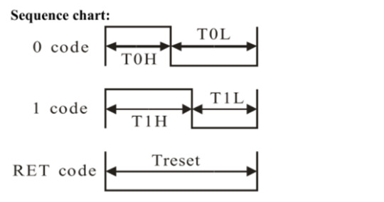
STM32F103C8T6
There are many materials and development documents about this chip on the Internet. Here is a brief introduction of this chip.
This is the development board of STM32F103C8T6, the purchase link:
https://item.taobao.com/item.htm?id=597967750760&ali_refid=a3_420434_1006:1189590055:N:jxREdm5V8MoL69LZxL%2Biz%2BQbG4S%2FtfkN:7ae5423c73cc44495581abdec5cd6265&ali_trackid=1_7ae5423c73cc44495581abdec5cd6265&spm=a230r.1.1957635.59
I'm not going to say much about this chip.The chip download code is j-link, as shown below:
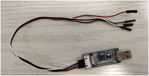
This is a simple version of j-link, only support SWD mode debugging and download, not support JTAG.But for the development of STM32 chip, SWD debugging method is enough.
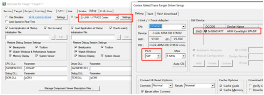
Download the code to the STM32 chip
Ensure the correct wiring of j-link and STM32F103C8T6, and then the chip can be identified in the KEIL development environment:
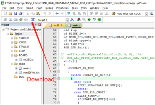
Click the download button to download the code to the chip:
STM32 code
The buttons and text in the display screen have corresponding addresses. In this project, the addresses of the display screen components are as follows:
#define RED_COLOR 0x07
#define ICON_WHITE_ADDR 0x02
#define ICON_RED_ADDR 0x03
#define ICON_GREEN_ADDR 0x04
#define ICON_BLUE_ADDR 0x05
#define TEXT_RED_ADDR 0x07
#define TEXT_GREEN_ADDR 0x08
#define TEXT_BLUE_ADDR 0x09
#define TEXT_WHITE_ADDR 0x06
#define SWITCH_ONOFF_ADDR 0x01
#define ICON_ON 0x01
#define ICON_OFF 0x00
u8 data_send[8]= {0xA5, 0x5A, 0x05, 0x82, 0x00, 0x00, 0x00,0x00};
Data sent to the display screen should be sent according to the corresponding format:
U8 data_send[8]= {0xA5, 0x5A, 0x05, 0x82, 0x00,0x00,0x00,0x00};
Data [4]\ data[5] is the high and low order of component addresses.
Data [6]\ data[7] is the data to be displayed by the component.
The main logical code will be provided below:
#include "stm32f10x.h"
#include "usart.h"
#include "delay.h"
#include "../BOARD/ws2812/ws2812.h"
struct RGB_COLOR
{
u8 C_RED;
u8 C_GREEN;
u8 C_BLUE;
u8 C_WHITE;
u8 C_RED_FLAG;
u8 C_GREEN_FLAG;
u8 C_BLUE_FLAG;
};
#define ICON_WHITE_ADDR 0x02
#define ICON_RED_ADDR 0x03
#define ICON_GREEN_ADDR 0x04
#define ICON_BLUE_ADDR 0x05
#define TEXT_RED_ADDR 0x07
#define TEXT_GREEN_ADDR 0x08
#define TEXT_BLUE_ADDR 0x09
#define TEXT_WHITE_ADDR 0x06
#define SWITCH_ONOFF_ADDR 0x01
#define ICON_ON 0x01
#define ICON_OFF 0x00
u8 data_send[8]= {0xA5, 0x5A, 0x05, 0x82, 0x00, 0x00, 0x00,0x00};
void UART1_Send_Array(u8 send_array[],unsigned char num)
{
u8 i=0;
while(i<num)
{
USART_SendData(USART1,send_array[i]);
while( USART_GetFlagStatus(USART1,USART_FLAG_TC)!= SET);
i++;
}
}
int main(void)
{
uart_init(115200);
delay_init();
struct RGB_COLOR USER_RGB_COLOR;
USER_RGB_COLOR.C_BLUE=0;
USER_RGB_COLOR.C_GREEN=0;
USER_RGB_COLOR.C_RED=0;
USER_RGB_COLOR.C_RED_FLAG=1;
USER_RGB_COLOR.C_GREEN_FLAG=1;
USER_RGB_COLOR.C_BLUE_FLAG=1;
u16 k,q;
u8 BLINK_2=0;
u8 USER_R=0,USER_G=0,USER_B=0,COLOR_TYPE=0,COLOR_DIR=0;
u8 blink_type=0;
u16 times=0;
RGB_LED_Init();
while(1)
{
if(USART_RX_END)
{
switch (USART_RX_BUF[5])
{
case 0x33:
PIXEL_NUM=USART_RX_BUF[8];
break;
case LED_ALL_ONOFF:
blink_type=0;
if(USART_RX_BUF[8]==0)
{
data_send[5]=ICON_RED_ADDR;
data_send[7]=ICON_OFF;
UART1_Send_Array(data_send,8);
data_send[5]=TEXT_RED_ADDR;
data_send[7]=0x00;
UART1_Send_Array(data_send,8);
data_send[5]=ICON_GREEN_ADDR;
data_send[7]=ICON_OFF;
UART1_Send_Array(data_send,8);
data_send[5]=TEXT_GREEN_ADDR;
data_send[7]=0x00;
UART1_Send_Array(data_send,8);
data_send[5]=ICON_BLUE_ADDR;
data_send[7]=ICON_OFF;
UART1_Send_Array(data_send,8);
data_send[5]=TEXT_BLUE_ADDR;
data_send[7]=0x00;
UART1_Send_Array(data_send,8);
USER_RGB_COLOR.C_BLUE=0;
USER_RGB_COLOR.C_GREEN=0;
USER_RGB_COLOR.C_RED=0;
data_send[5]=ICON_WHITE_ADDR;
data_send[7]=ICON_OFF;
UART1_Send_Array(data_send,8);
data_send[5]=TEXT_WHITE_ADDR;
data_send[7]=0x00;
UART1_Send_Array(data_send,8);
USER_RGB_COLOR.C_WHITE=0;
}
else
{
USER_RGB_COLOR.C_BLUE=0x32;
USER_RGB_COLOR.C_GREEN=0x10;
USER_RGB_COLOR.C_RED=0x24;
USER_RGB_COLOR.C_RED_FLAG=0;
USER_RGB_COLOR.C_GREEN_FLAG=0;
USER_RGB_COLOR.C_BLUE_FLAG=0;
data_send[5]=ICON_RED_ADDR;
data_send[7]=ICON_ON;
UART1_Send_Array(data_send,8);
data_send[5]=TEXT_RED_ADDR;
data_send[7]=0x24;
UART1_Send_Array(data_send,8);
data_send[5]=ICON_GREEN_ADDR;
data_send[7]=ICON_ON;
UART1_Send_Array(data_send,8);
data_send[5]=TEXT_GREEN_ADDR;
data_send[7]=0x10;
UART1_Send_Array(data_send,8);
data_send[5]=ICON_BLUE_ADDR;
data_send[7]=ICON_ON;
UART1_Send_Array(data_send,8);
data_send[5]=TEXT_BLUE_ADDR;
data_send[7]=0x32;
UART1_Send_Array(data_send,8);
}
RGB_LED_Write_24Bits(USER_RGB_COLOR.C_RED, USER_RGB_COLOR.C_GREEN, USER_RGB_COLOR.C_BLUE);
break;
case RED_COLOR:
blink_type=0;
if(USER_RGB_COLOR.C_RED_FLAG==1)
{
if(USART_RX_BUF[8]==0)
break;
}
data_send[5]=ICON_WHITE_ADDR;
data_send[7]=ICON_OFF;
UART1_Send_Array(data_send,8);
data_send[5]=TEXT_WHITE_ADDR;
data_send[7]=0x00;
UART1_Send_Array(data_send,8);
USER_RGB_COLOR.C_WHITE=0;
data_send[5]=SWITCH_ONOFF_ADDR;
data_send[7]=ICON_ON;
UART1_Send_Array(data_send,8);
data_send[5]=ICON_RED_ADDR;
if(USART_RX_BUF[8]>0)data_send[7]=ICON_ON;
else data_send[7]=ICON_OFF;
UART1_Send_Array(data_send,8);
USER_RGB_COLOR.C_RED=USART_RX_BUF[8];
USER_RGB_COLOR.C_RED_FLAG=0;
if(USER_RGB_COLOR.C_RED==0)USER_RGB_COLOR.C_RED_FLAG=1;
if((USER_RGB_COLOR.C_RED==0x00)&&(USER_RGB_COLOR.C_GREEN==0x00)&&(USER_RGB_COLOR.C_BLUE==0x00)&&(USER_RGB_COLOR.C_WHITE==0x00))
{
data_send[5]=SWITCH_ONOFF_ADDR;
data_send[7]=ICON_OFF;
UART1_Send_Array(data_send,8);
}
RGB_LED_Write_24Bits(USER_RGB_COLOR.C_RED, USER_RGB_COLOR.C_GREEN, USER_RGB_COLOR.C_BLUE); // Red
break;
case GREEN_COLOR:
blink_type=0;
if(USER_RGB_COLOR.C_GREEN_FLAG==1)
{
if(USART_RX_BUF[8]==0)
break;
}
data_send[5]=ICON_GREEN_ADDR;
if(USART_RX_BUF[8]>0)data_send[7]=ICON_ON;
else data_send[7]=ICON_OFF;
UART1_Send_Array(data_send,8);
data_send[5]=ICON_WHITE_ADDR;
data_send[7]=ICON_OFF;
UART1_Send_Array(data_send,8);
data_send[5]=TEXT_WHITE_ADDR;
data_send[7]=0x00;
UART1_Send_Array(data_send,8);
USER_RGB_COLOR.C_WHITE=0;
data_send[5]=SWITCH_ONOFF_ADDR;
data_send[7]=ICON_ON;
UART1_Send_Array(data_send,8);
USER_RGB_COLOR.C_GREEN=USART_RX_BUF[8];
USER_RGB_COLOR.C_GREEN_FLAG=0;
if(USER_RGB_COLOR.C_GREEN==0)USER_RGB_COLOR.C_GREEN_FLAG=1;
if((USER_RGB_COLOR.C_RED==0x00)&&(USER_RGB_COLOR.C_GREEN==0x00)&&(USER_RGB_COLOR.C_BLUE==0x00)&&(USER_RGB_COLOR.C_WHITE==0x00))
{
data_send[5]=SWITCH_ONOFF_ADDR;
data_send[7]=ICON_OFF;
UART1_Send_Array(data_send,8);
}
RGB_LED_Write_24Bits(USER_RGB_COLOR.C_RED, USER_RGB_COLOR.C_GREEN, USER_RGB_COLOR.C_BLUE); // Green
break;
case BLUE_COLOR:
blink_type=0;
if(USER_RGB_COLOR.C_BLUE_FLAG==1)
{
if(USART_RX_BUF[8]==0)
break;
}
data_send[5]=ICON_BLUE_ADDR;
if(USART_RX_BUF[8]>0)data_send[7]=ICON_ON;
else data_send[7]=ICON_OFF;
UART1_Send_Array(data_send,8);
data_send[5]=ICON_WHITE_ADDR;
data_send[7]=ICON_OFF;
UART1_Send_Array(data_send,8);
data_send[5]=TEXT_WHITE_ADDR;
data_send[7]=0x00;
UART1_Send_Array(data_send,8);
USER_RGB_COLOR.C_WHITE=0;
data_send[5]=SWITCH_ONOFF_ADDR;
data_send[7]=ICON_ON;
UART1_Send_Array(data_send,8);
USER_RGB_COLOR.C_BLUE=USART_RX_BUF[8];
USER_RGB_COLOR.C_BLUE_FLAG=0;
if(USER_RGB_COLOR.C_BLUE==0)USER_RGB_COLOR.C_BLUE_FLAG=1;
if((USER_RGB_COLOR.C_RED==0x00)&&(USER_RGB_COLOR.C_GREEN==0x00)&&(USER_RGB_COLOR.C_BLUE==0x00)&&(USER_RGB_COLOR.C_WHITE==0x00))
{
data_send[5]=SWITCH_ONOFF_ADDR;
data_send[7]=ICON_OFF;
UART1_Send_Array(data_send,8);
}
RGB_LED_Write_24Bits(USER_RGB_COLOR.C_RED, USER_RGB_COLOR.C_GREEN, USER_RGB_COLOR.C_BLUE); // Blue
break;
case WHITE_COLOR:
blink_type=0;
data_send[5]=ICON_WHITE_ADDR;
if(USART_RX_BUF[8]>0)data_send[7]=ICON_ON;
else data_send[7]=ICON_OFF;
UART1_Send_Array(data_send,8);
data_send[5]=ICON_RED_ADDR;
data_send[7]=ICON_OFF;
UART1_Send_Array(data_send,8);
data_send[5]=TEXT_RED_ADDR;
data_send[7]=0x00;
UART1_Send_Array(data_send,8);
data_send[5]=ICON_GREEN_ADDR;
data_send[7]=ICON_OFF;
UART1_Send_Array(data_send,8);
data_send[5]=TEXT_GREEN_ADDR;
data_send[7]=0x00;
UART1_Send_Array(data_send,8);
data_send[5]=ICON_BLUE_ADDR;
data_send[7]=ICON_OFF;
UART1_Send_Array(data_send,8);
data_send[5]=TEXT_BLUE_ADDR;
data_send[7]=0x00;
UART1_Send_Array(data_send,8);
USER_RGB_COLOR.C_BLUE=0;
USER_RGB_COLOR.C_GREEN=0;
USER_RGB_COLOR.C_RED=0;
USER_RGB_COLOR.C_RED_FLAG=1;
USER_RGB_COLOR.C_GREEN_FLAG=1;
USER_RGB_COLOR.C_BLUE_FLAG=1;
data_send[5]=SWITCH_ONOFF_ADDR;
data_send[7]=ICON_ON;
UART1_Send_Array(data_send,8);
USER_RGB_COLOR.C_WHITE=USART_RX_BUF[8];
if((USER_RGB_COLOR.C_RED==0x00)&&(USER_RGB_COLOR.C_GREEN==0x00)&&(USER_RGB_COLOR.C_BLUE==0x00)&&(USER_RGB_COLOR.C_WHITE==0x00))
{
data_send[5]=SWITCH_ONOFF_ADDR;
data_send[7]=ICON_OFF;
UART1_Send_Array(data_send,8);
}
RGB_LED_Write_24Bits(USER_RGB_COLOR.C_WHITE, USER_RGB_COLOR.C_WHITE, USER_RGB_COLOR.C_WHITE);
break;
case BLINK1:
blink_type=1;
data_send[5]=ICON_RED_ADDR;
data_send[7]=ICON_OFF;
UART1_Send_Array(data_send,8);
data_send[5]=TEXT_RED_ADDR;
data_send[7]=0x00;
UART1_Send_Array(data_send,8);
data_send[5]=ICON_GREEN_ADDR;
data_send[7]=ICON_OFF;
UART1_Send_Array(data_send,8);
data_send[5]=TEXT_GREEN_ADDR;
data_send[7]=0x00;
UART1_Send_Array(data_send,8);
data_send[5]=ICON_BLUE_ADDR;
data_send[7]=ICON_OFF;
UART1_Send_Array(data_send,8);
data_send[5]=TEXT_BLUE_ADDR;
data_send[7]=0x00;
UART1_Send_Array(data_send,8);
USER_RGB_COLOR.C_BLUE=0;
USER_RGB_COLOR.C_GREEN=0;
USER_RGB_COLOR.C_RED=0;
data_send[5]=ICON_WHITE_ADDR;
data_send[7]=ICON_OFF;
UART1_Send_Array(data_send,8);
data_send[5]=TEXT_WHITE_ADDR;
data_send[7]=0x00;
UART1_Send_Array(data_send,8);
USER_RGB_COLOR.C_WHITE=0;
data_send[5]=SWITCH_ONOFF_ADDR;
data_send[7]=ICON_ON;
UART1_Send_Array(data_send,8);
break;
case BLINK2:
blink_type=2;
data_send[5]=ICON_RED_ADDR;
data_send[7]=ICON_OFF;
UART1_Send_Array(data_send,8);
data_send[5]=TEXT_RED_ADDR;
data_send[7]=0x00;
UART1_Send_Array(data_send,8);
data_send[5]=ICON_GREEN_ADDR;
data_send[7]=ICON_OFF;
UART1_Send_Array(data_send,8);
data_send[5]=TEXT_GREEN_ADDR;
data_send[7]=0x00;
UART1_Send_Array(data_send,8);
data_send[5]=ICON_BLUE_ADDR;
data_send[7]=ICON_OFF;
UART1_Send_Array(data_send,8);
data_send[5]=TEXT_BLUE_ADDR;
data_send[7]=0x00;
UART1_Send_Array(data_send,8);
USER_RGB_COLOR.C_BLUE=0;
USER_RGB_COLOR.C_GREEN=0;
USER_RGB_COLOR.C_RED=0; ��
data_send[5]=ICON_WHITE_ADDR;
data_send[7]=ICON_OFF;
UART1_Send_Array(data_send,8);
data_send[5]=TEXT_WHITE_ADDR;
data_send[7]=0x00;
UART1_Send_Array(data_send,8);
USER_RGB_COLOR.C_WHITE=0;
data_send[5]=SWITCH_ONOFF_ADDR;
data_send[7]=ICON_ON;
UART1_Send_Array(data_send,8);
break;
case BLINK3:
blink_type=3;
data_send[5]=ICON_RED_ADDR;
data_send[7]=ICON_OFF;
UART1_Send_Array(data_send,8);
data_send[5]=TEXT_RED_ADDR;
data_send[7]=0x00;
UART1_Send_Array(data_send,8);
data_send[5]=ICON_GREEN_ADDR;
data_send[7]=ICON_OFF;
UART1_Send_Array(data_send,8);
data_send[5]=TEXT_GREEN_ADDR;
data_send[7]=0x00;
UART1_Send_Array(data_send,8);
data_send[5]=ICON_BLUE_ADDR;
data_send[7]=ICON_OFF;
UART1_Send_Array(data_send,8);
data_send[5]=TEXT_BLUE_ADDR;
data_send[7]=0x00;
UART1_Send_Array(data_send,8);
USER_RGB_COLOR.C_BLUE=0;
USER_RGB_COLOR.C_GREEN=0;
USER_RGB_COLOR.C_RED=0;
// USER_RGB_COLOR.C_RED_FLAG=1;
// USER_RGB_COLOR.C_GREEN_FLAG=1;
// USER_RGB_COLOR.C_BLUE_FLAG=1;
data_send[5]=ICON_WHITE_ADDR;
data_send[7]=ICON_OFF;
UART1_Send_Array(data_send,8);
data_send[5]=TEXT_WHITE_ADDR;
data_send[7]=0x00;
UART1_Send_Array(data_send,8);
USER_RGB_COLOR.C_WHITE=0;
data_send[5]=SWITCH_ONOFF_ADDR;
data_send[7]=ICON_ON;
UART1_Send_Array(data_send,8);
break;
case BLINK4:
blink_type=4;
data_send[5]=ICON_RED_ADDR;
data_send[7]=ICON_OFF;
UART1_Send_Array(data_send,8);
data_send[5]=TEXT_RED_ADDR;
data_send[7]=0x00;
UART1_Send_Array(data_send,8);
data_send[5]=ICON_GREEN_ADDR;
data_send[7]=ICON_OFF;
UART1_Send_Array(data_send,8);
data_send[5]=TEXT_GREEN_ADDR;
data_send[7]=0x00;
UART1_Send_Array(data_send,8);
data_send[5]=ICON_BLUE_ADDR;
data_send[7]=ICON_OFF;
UART1_Send_Array(data_send,8);
data_send[5]=TEXT_BLUE_ADDR;
data_send[7]=0x00;
UART1_Send_Array(data_send,8);
USER_RGB_COLOR.C_BLUE=0;
USER_RGB_COLOR.C_GREEN=0;
USER_RGB_COLOR.C_RED=0;
data_send[5]=ICON_WHITE_ADDR;
data_send[7]=ICON_OFF;
UART1_Send_Array(data_send,8);
data_send[5]=TEXT_WHITE_ADDR;
data_send[7]=0x00;
UART1_Send_Array(data_send,8);
USER_RGB_COLOR.C_WHITE=0;
data_send[5]=SWITCH_ONOFF_ADDR;
data_send[7]=ICON_ON;
UART1_Send_Array(data_send,8);
break;
default:
USART_RX_END=0;
USART_RX_STA=0;
break;
}
USART_RX_STA=0;
USART_RX_END=0;
}
else
{
if(blink_type==1)
{
times++;
if(times>=14)
{
times=0;
if(COLOR_DIR==0)
{
if(COLOR_TYPE==0)
{
USER_R++;
USER_G=0;
USER_B=0;
}
else if(COLOR_TYPE==1)
{
USER_R=0;
USER_G++;
USER_B=0;
}
else if(COLOR_TYPE==2)
{
USER_R=0;
USER_G=0;
USER_B++;
}
else if(COLOR_TYPE==3)
{
USER_R++;
USER_G++;
USER_B=0;
}
else if(COLOR_TYPE==4)
{
USER_R=0;
USER_G++;
USER_B++;
}
else if(COLOR_TYPE==5)
{
USER_R++;
USER_G=0;
USER_B++;
}
if((USER_R>=250)||(USER_G>=250)||(USER_B>=250))
{
COLOR_DIR=1;
}
}
else
{
if(COLOR_TYPE==0)
{
USER_R--;
USER_G=0;
USER_B=0;
}
else if(COLOR_TYPE==1)
{
USER_R=0;
USER_G--;
USER_B=0;
}
else if(COLOR_TYPE==2)
{
USER_R=0;
USER_G=0;
USER_B--;
}
else if(COLOR_TYPE==3)
{
USER_R--;
USER_G--;
USER_B=0;
}
else if(COLOR_TYPE==4)
{
USER_R=0;
USER_G--;
USER_B--;
}
else if(COLOR_TYPE==5)
{
USER_R--;
USER_G=0;
USER_B--;
}
if((USER_R==0x02)||(USER_G==0x02)||(USER_B==0x02))
{
COLOR_DIR=0;
COLOR_TYPE++;
if(COLOR_TYPE>5)
COLOR_TYPE=0;
}
}
RGB_LED_Write_24Bits(USER_R,USER_G,USER_B);
}
delay_ms(1);
}
else if(blink_type==2)
{
k++;
if(k>=150)
{
k=0;
q=200;
{
BLINK_2++;
if(BLINK_2>8)BLINK_2=0;
}
if(BLINK_2==0)
RGB_LED_Write_24Bits(q,0,0);
else if(BLINK_2==1)
RGB_LED_Write_24Bits(0,q,0);
else if(BLINK_2==2)
RGB_LED_Write_24Bits(0,0,q);
else if(BLINK_2==3)
RGB_LED_Write_24Bits(q,q,0);
else if(BLINK_2==4)
RGB_LED_Write_24Bits(0,q,q);
else if(BLINK_2==5)
RGB_LED_Write_24Bits(q,0,q);
else if(BLINK_2==6)
RGB_LED_Write_24Bits(q-100,q,0);
else if(BLINK_2==7)
RGB_LED_Write_24Bits(0,q-80,q);
else if(BLINK_2==8)
RGB_LED_Write_24Bits(q,0,q-120);
else if(BLINK_2==9)
RGB_LED_Write_24Bits(40,q-100,q-70);
else if(BLINK_2==10)
RGB_LED_Write_24Bits(q,100,q-80);
}
delay_ms(1);
}
else if(blink_type==3)
{
k++;
if(k>=1000)
{
k=0;
{
BLINK_2++;
if(BLINK_2>5)BLINK_2=0;
}
{
if(BLINK_2==0)
RGB_LED_Write_24Bits(q,0,0);
else if(BLINK_2==1)
RGB_LED_Write_24Bits(0,q,0);
else if(BLINK_2==2)
RGB_LED_Write_24Bits(0,0,q);
else if(BLINK_2==3)
RGB_LED_Write_24Bits(q,q,0);
else if(BLINK_2==4)
RGB_LED_Write_24Bits(0,q,q);
else if(BLINK_2==5)
RGB_LED_Write_24Bits(q,0,q);
}
}
delay_ms(1);
}
else if(blink_type==4)
{
k++;
if(k>=500)
{
k=0;
q=0;
BLINK_2++;
if(BLINK_2>5)BLINK_2=0;
}
q++;
if(q>=250)q=0;
if(BLINK_2==0)
RGB_LED_Write_24Bits(q,0,0);
else if(BLINK_2==1)
RGB_LED_Write_24Bits(0,q,0);
else if(BLINK_2==2)
RGB_LED_Write_24Bits(0,0,q);
else if(BLINK_2==3)
RGB_LED_Write_24Bits(q,q,0);
else if(BLINK_2==4)
RGB_LED_Write_24Bits(0,q,q);
else if(BLINK_2==5)
RGB_LED_Write_24Bits(q,0,q);
delay_ms(1);
}
else
{
}
}
}
}
Finally, the code is downloaded into the STM32 chip, and the completed circuit board is connected to the display screen, and the power supply is guaranteed to be stable. Then the brightness and color of the RGB lamp can be controlled through the STONE display module.
The final hardware connection diagram
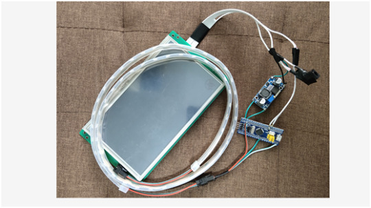
Running effect

0 notes
Text
STM32F103C8T6 development board, program arm stm32 arduino
Intro for STM32F103C8T6
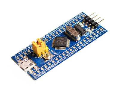
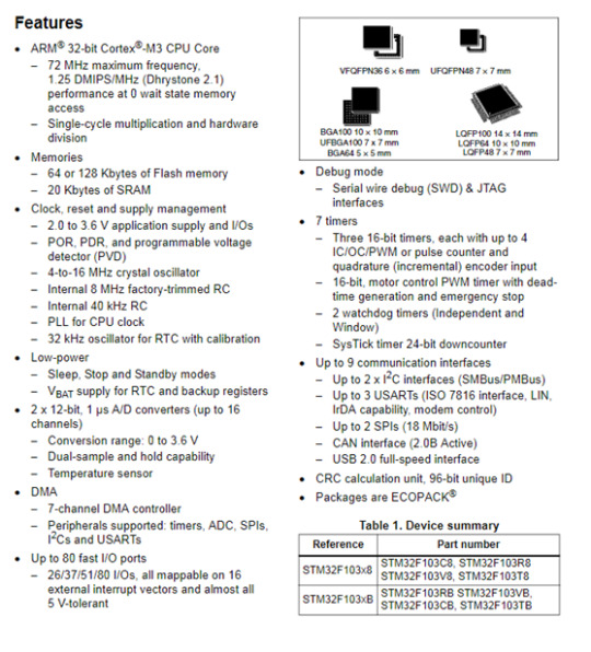
The STM32F103C8T6 is a development board for the ARM Cortex-M3 processor, designed to provide a low-cost platform that can still meet the requirements of many developers. These board's features make it ideal for a wide range of applications such as motor control, power management, medical and handheld equipment, PC and gaming peripherals, GPS platforms, industrial applications and more.
STM32F103C8T6 medium-density performance line family incorporates the high-performance ARM Cortex-M3 32-bit RISC core operating at a 72 MHz frequency, high-speed embedded memories (Flash memory up to 128 Kbytes and SRAM up to 20 Kbytes), and an extensive range of enhanced I/Os and peripherals connected to two APB buses. All devices offer two 12-bit ADCs, three general purpose 16-bit timers plus one PWM timer, as well as standard and advanced communication interfaces: up to two I2Cs and SPIs, three USARTs, an USB and a CAN. The devices operate from a 2.0 to 3.6 V power supply. They are available in both the –40 to +85 °C temperature range and the –40 to +105 °C extended temperature range. A comprehensive set of power-saving mode allows the design of low-power applications.
Tutorial to Program STM32F103C8T6 ARM STM32 arduino
STM32F103C8T6 is a very cheap but very fast ARM STM32 micro controller. You can run simple sketches very easy by following the steps below. 1. Download the latest Arduino IDE from arduino.cc and extract it. You can also download the Arduino IDE .exe file and install it to your computer. 2. After downloading the file from this link, extract it and copy the Arduino_STM32-master to your Arduino / hardware folder that you extract in the first step. If you have downloaded the .exe file then go to C:\Programs\Arduino\hardware. 3. Run the Arduino IDE, choose settings: 'Board: Generic STM32F103C series' 'Variant: STM32F103C8 (20k RAM, 64k Flash)' 'Upload method: Serial' 'Port: <the COM port of your USB-to-serial adapter>' 4. Go to File->Exampls A_STM32_Exampls->Digital->Blink and change the PB1 to PC13. 5. Put Boot1 to 1 by moving the jumper for 0 to 1, Press the Reset button and hit Upload on the Arduino IDE. After uploading if all went well the LED will blink every 100ms. Put Boot1 to 0 again so the next time you power up the micro controller the program will star automatically. You can also try to read an analog value. Go to File->Exampls A_STM32_Exampls->Analog->AnalogInSerial. Change the const int analogInputPin = 15; to const int analogInputPin = PA0; and hit upload. Open the Serial Monitor on the Arduino IDE, the value will be from 0 to 4095, it has 4 times the resolution of an arduino.
Features of STM32F103C8T6
Embedded Flash memory
- Up to 128 Kbytes of embedded Flash is available for storing programs and data.
Embedded SRAM
- Up to 20 Kbytes of embedded SRAM accessed (read/write) at CPU clock speed with 0 wait states.
Boot modes
At startup, boot pins are used to select one of three boot options:
- Boot from User Flash
- Boot from System Memory
- Boot from SRAM
The boot loader is located in System Memory. It is used to reprogram the Flash memory by using the USART.
Power supply schemes
- VDD = 2.0 to 3.6 V: external power supply for I/Os and the internal regulator. Provided externally through VDD pins.
- VSSA, VDDA = 2.0 to 3.6 V: external analog power supplies for ADC, Reset blocks, RCs and PLL. In VDD range (ADC is limited at 2.4 V).
- VBAT = 1.8 to 3.6 V: power supply for RTC, external clock 32 kHz oscillator and backup registers (through power switch) when VDD is not present.
>>Read more
0 notes